史上最新(V8.96)最全:超高性价比的Keil MDK STM Cortex-Mx系列芯片调试工具SEGGER JLink(<10CNY)的使用从零开始(附免费最新JLINK驱动程序)
本文详细介绍了在Keil MDK中使用J-Link调试器的完整配置流程。主要内容包括:安装Keil MDK和J-Link软件包;连接调试器与目标板;在Keil中配置J-Link调试参数(接口类型、时钟速度等);下载程序到目标芯片的操作步骤;以及基本的调试功能使用说明。文章还提供了常见问题排查方法,如连接失败、Flash下载异常等情况的解决方案。通过本指南,开发者可以快速掌握J-Link在Keil环
·
第一部分:安装准备
-
安装 Keil MDK (µVision):
- 确保你已经从 Arm 官网下载并安装了最新(或你项目所需的)版本的 Keil MDK (µVision) 软件。
- 安装过程中,请按照提示进行,并记住你的安装路径(通常是
C:\Keil_v5)。 - 安装完成后,确保 Keil MDK 的许可证已激活(评估版或商业版均可进行调试)。
-
下载 J-Link 软件包:
- 访问 SEGGER 官方网站的下载页面。
- 找到并下载适用于 Windows 的最新版 J-Link Software and Documentation Pack。
- 选择与你的系统位数(32位或64位)相匹配的安装程序。
- 最新版本8.96 https://www.segger.com/downloads/jlink/
Windows版本:https://www.segger.com/downloads/jlink/JLink_Windows_V896_x86_64.exe
-
硬件:
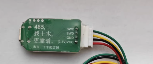
- J-Link 调试器:
Segger的调试器太贵,某宝有平替,不能做广告,自己去搜,还是typeC接口的,不到10元。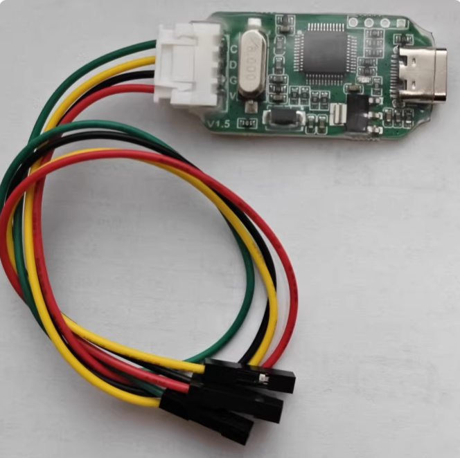
将 J-Link 调试器通过 USB 线连接到你的电脑。首次连接时,Windows 通常会尝试自动安装驱动,但可能不完整或不正确,因此需要后续手动安装 SEGGER 的驱动。 - 目标板: 将 J-Link 调试器的调试接口连接到你的目标开发板的调试接口上。
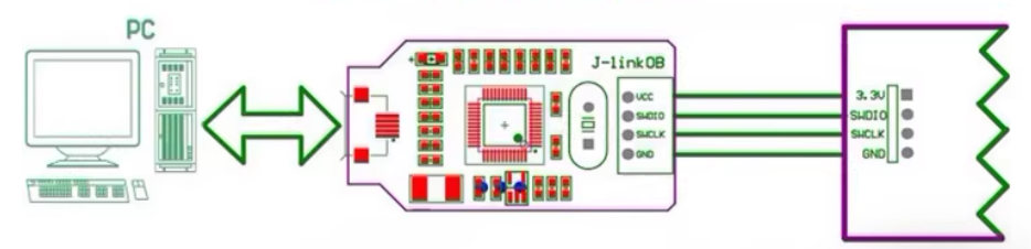
SWC = SCK
SWD = DIO
不要连错
- J-Link 调试器:
第二部分:安装 J-Link 驱动和软件
-
运行安装程序:
- 找到你下载的 J-Link Software and Documentation Pack 安装程序,并安装,建议按照缺省路径安装,并不大。
- 双击运行安装程序,一路下一步即可,安装程序会找到Keil并提示你更新调试器对应的DLL,这时一定要选择确认即可
-
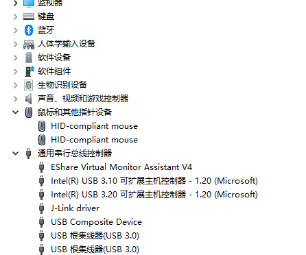
验证驱动安装:
- 将 J-Link 调试器连接到电脑 USB 口,如果已经插入,则重新拔插一下激活驱动。
- 打开 Windows 的 “设备管理器”。
- 展开 “通用串行总线控制器” 或 “其他设备”。
- 你应该能看到一个名为 “J-Link driver” 或 “SEGGER J-Link” 的设备。
第三部分:在 Keil MDK 中配置项目使用 J-Link
-
创建/打开 Keil 项目:
- 启动 Keil µVision。
- 打开你已有的项目,或者创建一个新项目(选择正确的目标设备,本例采用 STM32F411CE)。
-
配置项目选项 - Debug 标签页:
- 在 Keil 菜单栏,点击 “Project” -> “Options for Target ‘Target 1’” (或你的目标名称)。
- 在弹出的窗口中,点击 “Debug” 标签页。
- 在 “Use” 下拉菜单中,选择 “J-LINK / J-TRACE Cortex”。
- 如果你需要调试程序,则要确保 “Run to main()” 选项通常是勾选的(这样调试启动后会停在
main函数开头)。否则可不要勾选。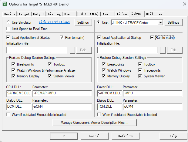
- 点击 “Settings” 按钮 (在 “Use” 下拉菜单旁边)。这将打开 J-Link 配置窗口。
-
配置 J-Link 设置:
如果显示不出SN和Device,那说明你的驱动没有安装好,要重新安装。
dll:会显示你安装的版本号,截止2025年12月28日,最新版本就是8.96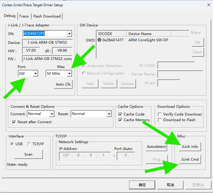
- “Target Interface”: 选择你的目标板实际使用的调试接口类型,通常是 “SWD” (Serial Wire Debug),因为它引脚少,速度快。
- “Port”: 必须选SW,不能选JTAG。如果电脑连接了多个 J-Link 或设备,可能需要选择正确的端口号(通常只有一个时自动选择)。
- “Max Clock Speed”: 设置调试时钟频率。对于初学者,可以先设置为一个较低的值以保证稳定性,如 “1 MHz”。如果连接稳定,可以尝试提高到 “4 MHz” 或更高(参考你的目标芯片手册支持的最高调试速度)。这个芯片具备自动调整时钟的能力,按“Auto Clk”即可自动选取,惊喜的是这个调试器支持50MHz!
- “Debug Adapter”: 显示连接的 J-Link 型号和固件版本信息。
- “Download Options”: 根据实际情况勾选 “Verify Code Download” 和 “Download to Flash” 通常是勾选的。
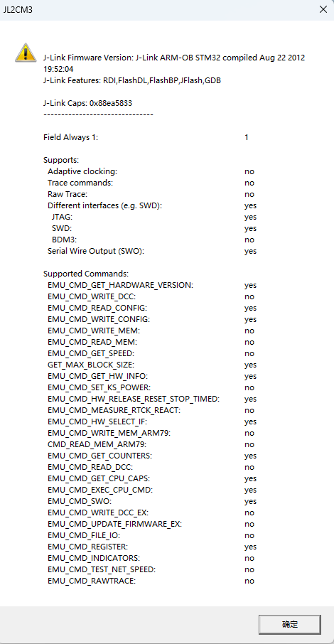
- “Jlink Info”:显示该调试器信息
- “Jlink Cmd”打开极其强大的Jlink 命令行窗口(单独开篇介绍)
SEGGER J-Link Commander V8.16 (Compiled Feb 26 2025 12:08:35) DLL version V8.96, compiled Dec 18 2025 16:46:38 Connecting to J-Link via USB...O.K. Firmware: J-Link ARM-OB STM32 compiled Aug 22 2012 19:52:04 Hardware version: V7.00 J-Link uptime (since boot): N/A (Not supported by this model) S/N: -1 License(s): RDI,FlashDL,FlashBP,JFlash,GDB VTref=3.300V Type "connect" to establish a target connection, '?' for help J-Link>? Available commands are: Command name Command syntax Command function ---------------------- ? ? [<Command>] Show information about all or specific commands. Exit Exit Close J-Link connection and quit. ExitOnError EoE <1/0> Exit on error. Sleep Sleep <Delay> Waits the given time (in milliseconds). Log Log <filename> Enables log to file. ExpDevList ExpDevList <Filename> Export device names from DLL internal device list to text file. ExpDevListXML ExpDevListXML <Filename> Export device names from DLL internal device list to XML file. USB USB [<SN>] Connect to J-Link via USB. IP IP <IPAddr|RemoteServerString> Connect to J-Link via TCP/IP or to Remote Server. SelectProbe SelectProbe [<Interface0> <Interface1> ...] Show list of all connected probes via specified interface. The probe to communicate with can then be selected. ShowEmuList ShowEmuList [<Interface0> <Interface1> ...] Show list of all connected probes via specified interface. Power Power <On|Off> [perm] Switch power supply for target. VTREF VTREF <Value[mV]>. 0 == Auto detection Set fixed value for VTref on J-Link. VCOM VCOM <enable|disable> Enable/disable VCOM. Takes effect after power cycle of the probe. ShowFWInfo ShowFWInfo Show firmware info. ShowHWStatus ShowHWStatus Show hardware status. IPAddr IPAddr Show/Assign IP address and subnetmask of/to connected probe. GWAddr GWAddr Show/Assign network gateway address of/to connected probe. DNSAddr DNSAddr Show/Assign network DNS server address of/to connected probe. ShowConf ShowConf Show configuration of the connected probe. Calibrate Calibrate Calibrate the target current measurement. Reboot Reboot [<Timeout[ms]>] Reboot the J-Link/J-Trace/Flasher. BootMode BootMode <Mode>. 0 == J-Link, 1 == CMSIS-DAPv1, 2 == CMSIS-DAPv2 Set boot mode to J-Link/CMSIS-DAPv1/CMSIS-DAPv2. Uptime Uptime Show current J-Link uptime since boot. Connect Connect Connect to target device. Device Device <DeviceName> Select specific device J-Link shall connect to. SelectInterface SelectInterface <Interface> Select target interface. Speed Speed <freq|auto|adaptive> Set target interface speed. LE LE Change mode to little endian. BE BE Change mode to big endian. Halt Halt Halt CPU. IsHalted IsHalted Return current CPU state. WaitHalt WaitHalt [<TimeoutMs>] (default: 1000 ms) Wait until CPU is halted or timeout is reached. Go Go Start CPU if halted. Reset Reset Reset CPU. ResetX ResetX <DelayAfterReset> Reset CPU with delay after reset. RSetType RSetType <Type> Set the current reset type. Step Step [<NumSteps> (decimal)] (default is 1) Execute step(s) on the CPU. IS IS Identify length of scan chain select register. MS MS <Scan chain> Measure length of scan chain. Regs Regs Display CPU register contents. RReg RReg <RegName> Read register. WReg WReg <RegName>, <Value> Write register. MoE MoE Shows mode-of-entry (CPU halt reason). SetBP SetBP <addr> [A/T] [S/H] Set breakpoint. ClearBP ClearBP <BP_Handle> Clear breakpoint. SetWP SetWP <Addr> [R/W] [<Data> [<D-Mask>] [A-Mask]] Set Watchpoint. ClearWP ClearWP <WP_Handle> Clear watchpoint. VCatch VCatch <Value> Write vector catch. SetPC SetPC <Addr> Set the PC to specified value. ReadAP ReadAP <RegIndex> Read CoreSight AP register. Note: First read returns data of the previous read. An additional read of DP reg 3 is necessary to get the data. WriteAP WriteAP <RegIndex> Write CoreSight AP register. ReadDP ReadDP <RegIndex> Read CoreSight DP register. Note: SWD: Data is returned immediately. JTAG: Data of the previous read is returned. An additional read of DP reg 3 is necessary to get the data. WriteDP WriteDP <RegIndex> Write CoreSight DP register. RCP15Ex RCE <Op1>, <CRn>, <CRm>, <Op2> Read CP15 register. WCP15Ex WCE <Op1>, <CRn>, <CRm>, <Op2>, <Data> Write CP15 register. Term Term Visualize printf output using DCC (SEGGER DCC handler running on target). Mem Mem [<Zone>:]<Addr>, <NumBytes> (hex) Read memory and show corresponding ASCII values. Mem8 Mem8 [<Zone>:]<Addr>, <NumBytes> (hex) Read 8-bit items. Mem16 Mem16 [<Zone>:]<Addr>, <NumItems> (hex) Read 16-bit items. Mem32 Mem32 [<Zone>:]<Addr>, <NumItems> (hex) Read 32-bit items. Write1 W1 [<Zone>:]<Addr>, <Data> (hex) Write 8-bit items. Write2 W2 [<Zone>:]<Addr>, <Data> (hex) Write 16-bit items. Write4 W4 [<Zone>:]<Addr>, <Data> (hex) Write 32-bit items. Write8 W8 [<Zone>:]<Addr>, <Data> (hex) Write 64-bit items. JTAGConf JTAGConf <IRpre>, <DRpre> Set number of IR/DR bits before Target device. JTAGId JTAGId Read JTAG Id. WJTAGIR WJTAGIR <Instruction(hex)>, [<IRLen(dec)>] (default IRLen=4) Write JTAG command (IR). WJTAGDR WJTAGDR <Data64(hex)>, <NumBits(dec)> Write JTAG data (DR). WJTAGRaw WJTAGRaw <NumBits(dec)> <TMS(hex)> <TDI(hex)> Write Raw JTAG data (LSB first). ResetTAP ResetTAP Reset TAP Controller using state machine (111110). ResetTRST ResetTRST Reset TAP Controller using nTRST. ICE ICE Show state of the embedded ICE macrocell (ICE breaker). ReadICE RI <RegIndex>(hex) Read Ice reg. WriteICE WI <RegIndex>, <Data>(hex) Write Ice reg. STraceStart STraceStart STRACE - Starts STRACE STraceStop STraceStop STRACE - Stops STRACE STraceRead STraceRead [<NumItems>] STRACE - Reads collected STRACE data SWOSpeed SWOSpeed SWO - Show supported speeds. SWOStart SWOStart [<Speed>]. Default: <Speed> == Autodetect SWO - Start. SWOStop SWOStop SWO - Stop. SWOStat SWOStat SWO - Display SWO status. SWORead SWORead SWO - Read and display SWO data. SWOShow SWOShow SWO - Read and analyze SWO data. SWOFlush SWOFlush SWO - Flush data. SWOView SWOView SWO - View terminal data. Erase Erase [<SAddr>, <EAddr>] Erase flash (range) of selected device. LoadFile LoadFile <FileName>, [<Addr> (.bin only)]. Load data file into target memory. Supported ext.: *.bin, *.mot, *.hex, *.srec, *.elf, *.out, *.axf SaveBin SaveBin <filename>, <addr>, <NumBytes> Save target memory range into binary file. VerifyBin VerifyBin <filename>, <addr> Verfy if specified .bin file is at the specified target memory location. FWrite FWrite <EmuFile> <HostFile> [<Offset> [<NumBytes>]] (Flasher only) Write file to emulator. FRead FRead <EmuFile> <HostFile> [<Offset> [<NumBytes>]] (Flasher only) Read file from emulator. FShow FShow <FileName> [<Offset> [<NumBytes>]] (Flasher only) Read and display file from emulator. FDelete FDelete <FileName> (Flasher only) Delete file on emulator. FSize FSize <FileName> (Flasher only) Display size of file on emulator. FList FList (Flasher only) List directory on emulator. FDiskInfo FDiskInfo (Flasher only) Lists storage usage of Flasher (occupied / free etc.). FFormat FFormat (Flasher only) Formats the Flasher FS. SecureArea SecureArea <Operation> (Flasher only) Creates/Removes secure area on probe. PowerTrace PowerTrace <LogFile> [<ChannelMask> <RefCountSel>] Perform power trace (not supported by all models) TestWSpeed TestWSpeed [<Addr> [<Size>]] Measure download speed into target memory. TestRSpeed TestRSpeed [<Addr> [<Size>] [<NumBlocks>]] Measure upload speed from target memory. TestCSpeed TestCSpeed [<RAMAddr>] Measure CPU speed. TestNWSpeed TestNWSpeed [<NumBytes> [<NumReps>]] Measure network download speed. TestNRSpeed TestNRSpeed [<NumBytes> [<NumReps>]] Measure network upload speed. MR MR Measure RTCK react time. Clock Clock TCK - Clock. Clock00 Clock00 TCK - Clock with TDI = TMS = 0. ClrTCK ClrTCK TCK - Clear. SetTCK SetTCK TCK - Set. ClrTDI ClrTDI TDI - Clear. SetTDI SetTDI TDI - Set. ClrTMS ClrTMS TMS - Clear. SetTMS SetTMS TMS - Set. ClrTRST ClrTRST TRST - Clear. SetTRST SetTRST TRST - Set. ClrRESET ClrRESET RESET - Clear. SetRESET SetRESET RESET - Set. ---------------------- J-Link> - “Flash Download”: Keil 会根据你的目标芯片自动加载 Flash 编程算法并设置所需 RAM和下载算法。如果下载失败,可能需要检查这里是否分配了足够的 RAM 地址空间(但初学者很少遇到)。Reset and Run一般要勾选,否则你的程序下载下去不会运行,必须人工按一下复位按钮。初学者会感到困惑。
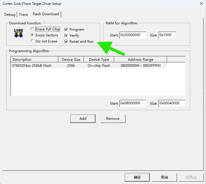
- “Programming Algorithm”编程算法是自动选择的,一般不需要改动。如果和你的设备不符合,“Programming Algorithm”: 点击 “Add” 按钮。在弹出的列表中,找到并选择与你目标芯片 Flash 型号匹配的编程算法,图中显示我的STM32F411的flash算法。如果找不到,请检查是否安装了对应芯片的设备支持包。
- 点击 “OK” 关闭 Flash Download 设置窗口。
- 回到 Utilities 标签页,点击 “OK” 保存设置。
- 编译完程序后,按
 按钮下载程序
JLink info:
------------
DLL: V8.96 , compiled Dec 18 2025 16:46:38
Firmware: J-Link ARM-OB STM32 compiled Aug 22 2012 19:52:04
Hardware: V7.00
Feature(s) : RDI,FlashDL,FlashBP,JFlash,GDB

* JLink Info: InitTarget() start
* JLink Info: SWD selected. Executing JTAG -> SWD switching sequence.
* JLink Info: DAP initialized successfully.
* JLink Info: InitTarget() end - Took 21.1ms
* JLink Info: Found SW-DP with ID 0x2BA01477
* JLink Info: DPv0 detected
* JLink Info: CoreSight SoC-400 or earlier
* JLink Info: Scanning AP map to find all available APs
* JLink Info: AP[1]: Stopped AP scan as end of AP map has been reached
* JLink Info: AP[0]: AHB-AP (IDR: 0x24770011, ADDR: 0x00000000)
* JLink Info: Iterating through AP map to find AHB-AP to use
* JLink Info: AP[0]: Core found
* JLink Info: AP[0]: AHB-AP ROM base: 0xE00FF000
* JLink Info: CPUID register: 0x410FC241. Implementer code: 0x41 (ARM)
* JLink Info: Found Cortex-M4 r0p1, Little endian.
* JLink Info: FPUnit: 6 code (BP) slots and 2 literal slots
* JLink Info: CoreSight components:
* JLink Info: ROMTbl[0] @ E00FF000
* JLink Info: [0][0]: E000E000 CID B105E00D PID 000BB00C SCS-M7
* JLink Info: [0][1]: E0001000 CID B105E00D PID 003BB002 DWT
* JLink Info: [0][2]: E0002000 CID B105E00D PID 002BB003 FPB
* JLink Info: [0][3]: E0000000 CID B105E00D PID 003BB001 ITM
* JLink Info: [0][4]: E0040000 CID B105900D PID 000BB9A1 TPIU
* JLink Info: [0][5]: E0041000 CID B105900D PID 000BB925 ETM
ROMTableAddr = 0xE00FF000
* JLink Info: Reset type: NORMAL (https://kb.segger.com/J-Link_Reset_Strategies)
* JLink Info: Reset: Halt core after reset via DEMCR.VC_CORERESET.
* JLink Info: Reset: Reset device via AIRCR.SYSRESETREQ.

Target info:
------------
Device: STM32F401RCTx
VTarget = 3.300V
State of Pins:
TCK: 0, TDI: 0, TDO: 1, TMS: 0, TRES: 1, TRST: 0
Hardware-Breakpoints: 6
Software-Breakpoints: 8192
Watchpoints:          4
JTAG speed: 4000 kHz

* JLink Info: Memory map 'after startup completion point' is active
Erase Done.
Programming Done.
Verify OK.
* JLink Info: Memory map 'before startup completion point' is active
* JLink Info: Reset type: NORMAL (https://kb.segger.com/J-Link_Reset_Strategies)
* JLink Info: Reset: Halt core after reset via DEMCR.VC_CORERESET.
* JLink Info: Reset: Reset device via AIRCR.SYSRESETREQ.
* JLink Info: Memory map 'after startup completion point' is active
Application running ...
* JLink Info: OnDisconnectTarget() start
* JLink Info: OnDisconnectTarget() end - Took 1.23ms
Flash Load finished at 19:34:28
第四部分:使用 J-Link 进行调试
-
编译项目:
- 在开始调试前,确保你的项目代码没有错误。点击 Keil 工具栏上的 “Rebuild” (通常是带红色箭头的按钮) 或按 F7 键编译整个项目。编译输出窗口应显示 “0 Error(s), 0 Warning(s)”。
-
启动调试会话:
- 点击 Keil 工具栏上的 “Start/Stop Debug Session” 按钮
 或按 Ctrl + F5。
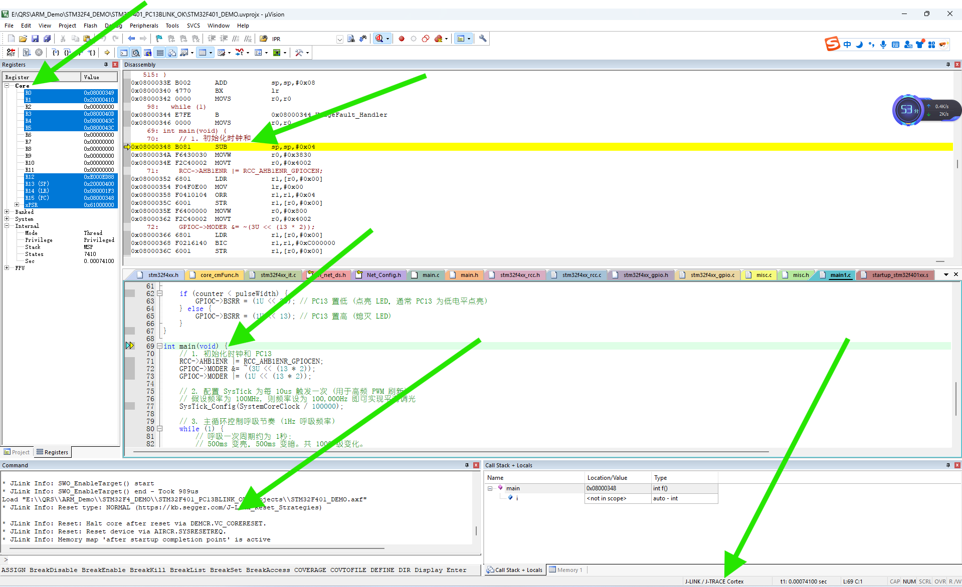
- 首次启动时,Keil 会尝试通过 J-Link 连接到你的目标板。如果一切配置正确,你应该会看到:
- 调试工具栏出现。
- 代码窗口会打开并停在
main函数的开头(如果设置了Run to main())。 - 寄存器窗口、反汇编窗口等可能会自动打开。
- 输出窗口的 “Command” 页签会显示 J-Link 的连接信息和初始化过程。
- 点击 Keil 工具栏上的 “Start/Stop Debug Session” 按钮
-
基本调试操作:
- 复位目标 (Reset): 点击调试工具栏上的复位按钮
 。这将复位目标芯片的 CPU。
 - 全速运行 (Run): 点击调试工具栏上的 “Run” 按钮 (绿色右箭头) 或按 F5。程序将开始全速运行,直到遇到断点或你手动停止。
- 停止运行 (Stop): 当程序运行时,点击调试工具栏上的 “Stop” 按钮 (红色方块) 或按 Esc 键可以停止程序运行。程序会停在当前执行的代码行。
- 单步执行:
- Step Over (F10): 执行当前行代码。如果当前行是函数调用,则执行整个函数并停在下一行。
- Step Into (F11): 执行当前行代码。如果当前行是函数调用,则进入该函数内部的第一行。
- Step Out (Ctrl + F11): 执行完当前函数剩下的部分,并跳出该函数,停在调用它的下一行。
- 设置断点 (Breakpoint): 在代码窗口左侧的灰色区域(行号旁边)点击鼠标,可以设置(红色实心圆)或取消(红色空心圆)断点。程序运行到断点处会自动停止。
- 查看变量 (Watch): 打开 “Watch 1” 窗口(菜单 View -> Watch Windows -> Watch 1)。在窗口的空白行输入变量名(如
myVariable),程序运行时或停止时可以看到变量的当前值。 - 查看内存 (Memory): 打开 “Memory” 窗口(菜单 View -> Memory Windows -> Memory 1)。在地址输入框中输入你想查看的内存地址(如
0x20000000),回车后可以看到该地址开始的内存内容。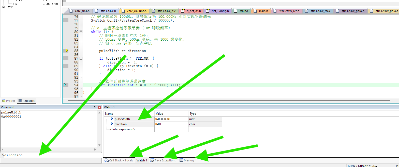
- 复位目标 (Reset): 点击调试工具栏上的复位按钮
-
结束调试:
- 点击调试工具栏上的 “Start/Stop Debug Session” 按钮或按 Ctrl + F5 结束调试会话,回到编辑模式。
- 点击调试工具栏上的 “Start/Stop Debug Session” 按钮
第五部分:常见问题排查
- 连接失败 / J-Link not found:
- 检查 J-Link 是否通过 USB 连接到电脑,USB 线是否完好。
- 检查 J-Link 和目标板之间的调试线(SWD/JTAG)是否连接正确、牢固。特别注意 SWD 接口的
SWCLK(时钟) 和SWDIO(数据) 线是否接对。 参考你的开发板手册。 - 确保目标板已正确供电(单独供电)。
- 在设备管理器中检查 J-Link 驱动是否安装正确(无黄色感叹号)。
- 尝试重启 Keil MDK 和电脑。
- 在 Keil Debug 设置的 J-Link 配置中,降低时钟速度 (如 100 kHz)。
- 尝试更换 USB 接口或 USB 线。
- Flash 下载失败:
- 最重要的: 确认在 “Utilities” 标签页配置了正确的 Flash 编程算法。
- 检查目标芯片型号选择是否正确。
- 确保目标板供电稳定充足。
- 在 J-Link 配置中尝试降低时钟速度。
- 检查调试线连接是否可靠。
- 尝试复位目标板后再下载。
- 调试时程序行为异常:
- 检查代码逻辑是否有误。
- 检查是否在正确的时钟频率下运行。
- 检查外设初始化是否正确。
- 利用断点和变量监视功能逐步排查。
希望这份详细的指南能帮助你顺利地在 Keil MDK 中使用 SEGGER J-Link 调试器进行开发!遇到问题时,耐心检查连接和配置细节通常是解决问题的关键。

智能硬件社区聚焦AI智能硬件技术生态,汇聚嵌入式AI、物联网硬件开发者,打造交流分享平台,同步全国赛事资讯、开展 OPC 核心人才招募,助力技术落地与开发者成长。
更多推荐
 8
8 0
0- 0


 已为社区贡献1条内容

所有评论(0)