定时器与PWM
本文介绍了基于STM32F103C8T6芯片的两个实验:1)通过定时器实现多任务并发控制,包括5秒定时发送串口消息和2秒定时LED闪烁;2)利用PWM技术实现呼吸灯效果。实验详细展示了使用STM32CubeMX进行硬件配置、Keil编写代码的完整流程,重点讲解了定时器中断回调函数和PWM占空比调节的实现方法。通过实践,作者体会到嵌入式开发中软硬件协同的重要性,掌握了调试技巧,并构建了STM32外设
一、stm32定时器实现点灯及串口通信
1、实验任务:
通过定时器Timer方式实现时间的精准控制,相当于给CPU上了一个闹钟,CPU平时处理其它任务,当定时时间到了以后,处理定时相关的任务。请设置一个5秒的定时器,每隔5秒从串口发送“hello windows!”;同时设置一个2秒的定时器,让LED等周期性地闪烁,实现一个多任务并发运行的功能。
2、工程建立
(1)cubemx创立新项目选择实验所用芯片,本实验采用stm32f103c8t6芯片
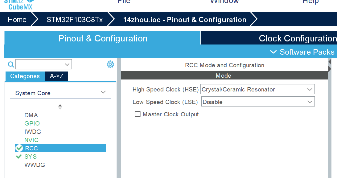
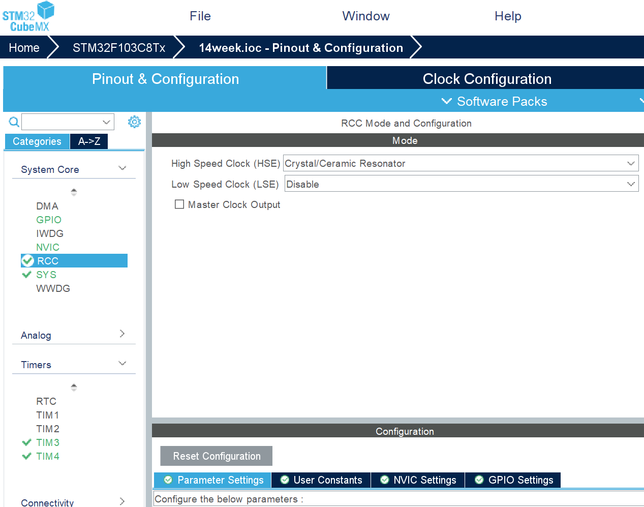
(2)配置RCC
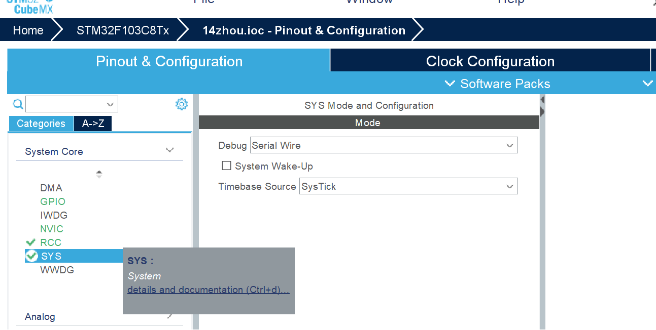
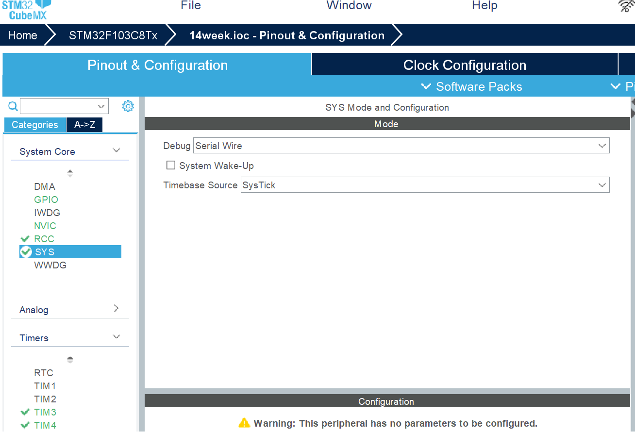
(3)配置SYS
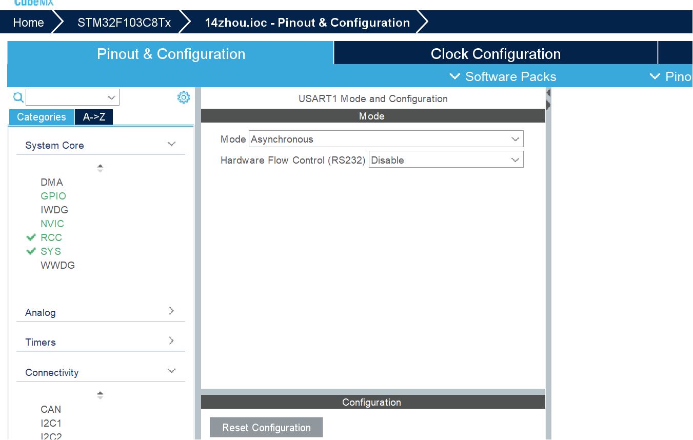
(4)配置USART1
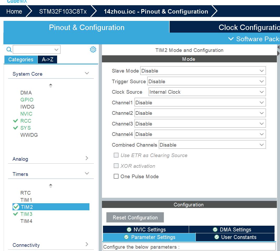
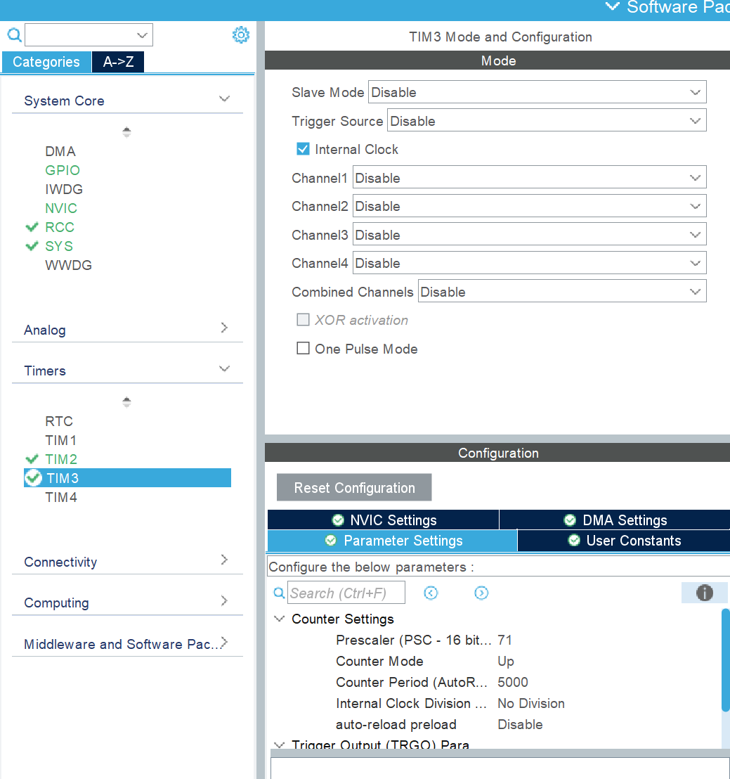
(5)分别配置TIM1、TIM2
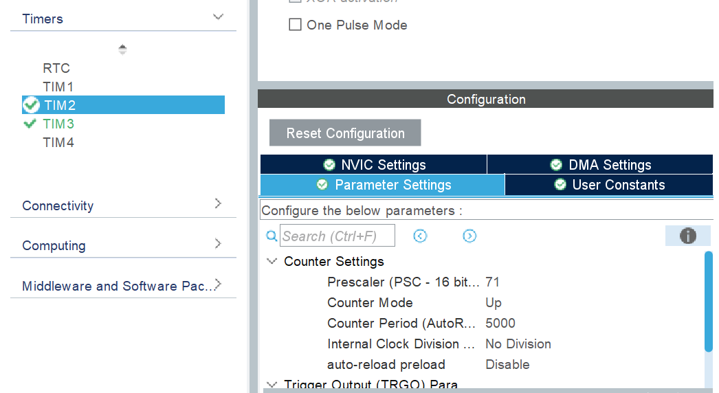
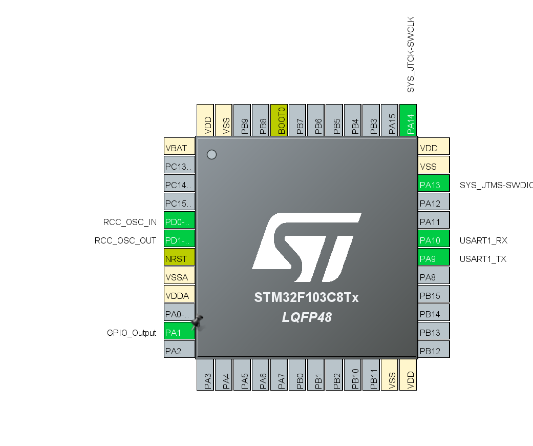
(6)配置引脚
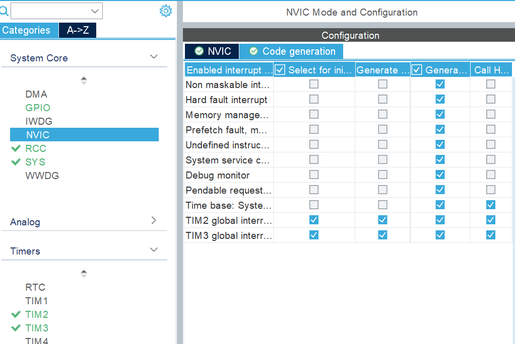
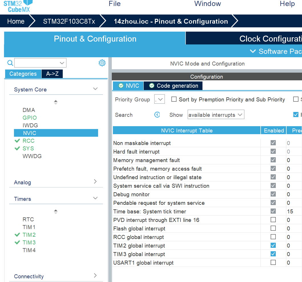
(7) 配置NVIC
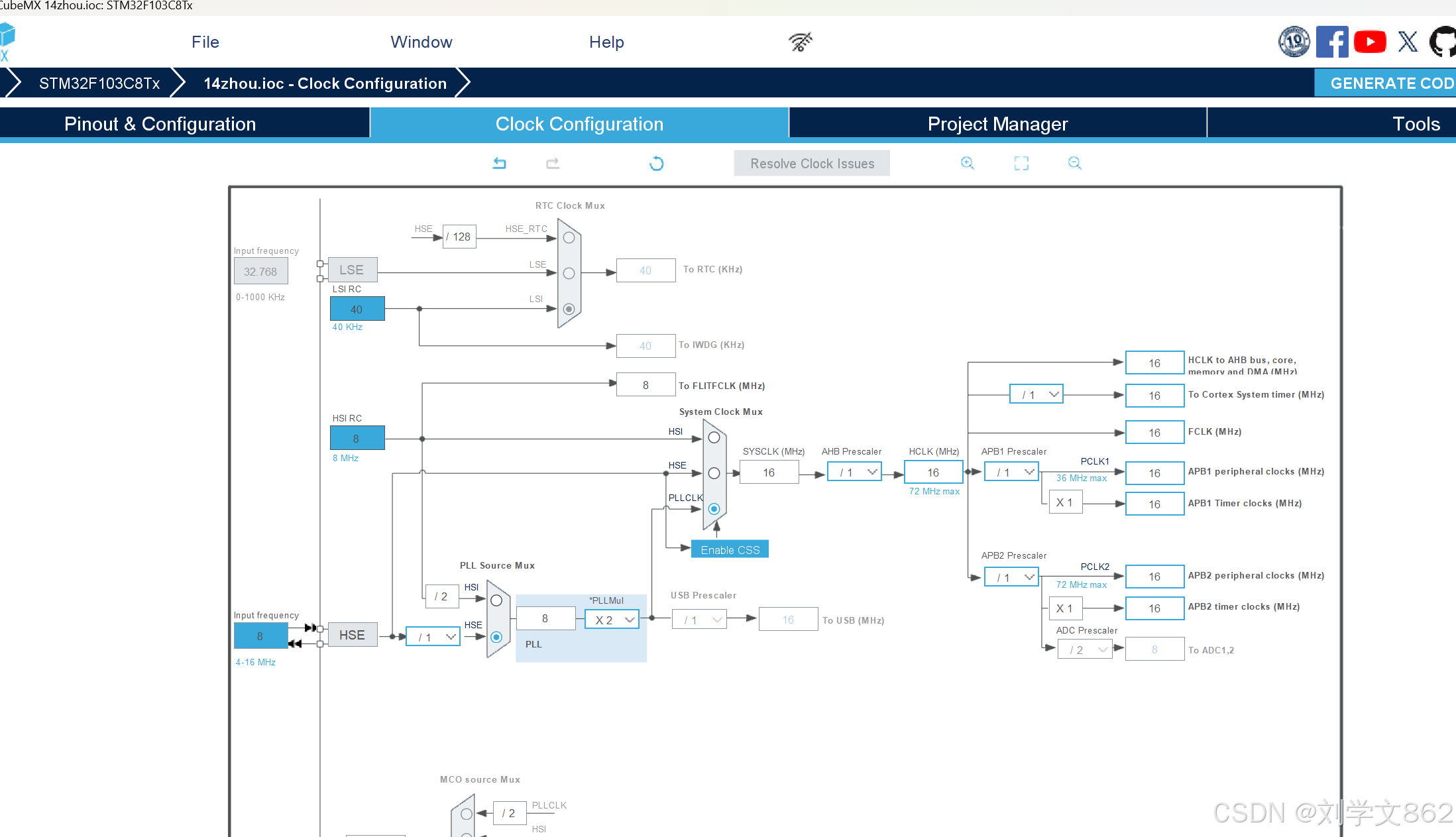
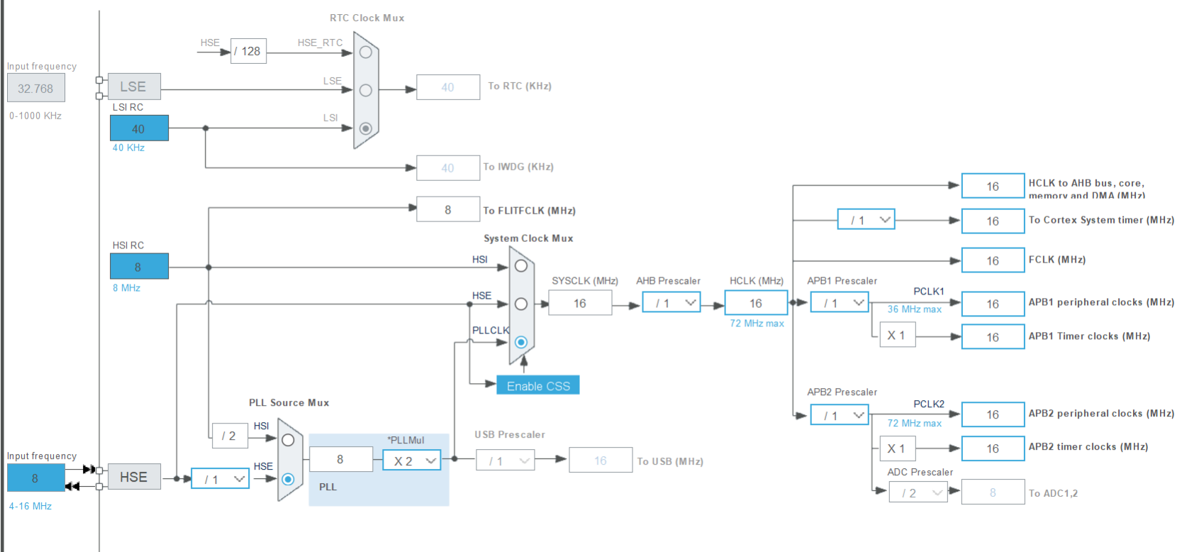
(8)时钟配置
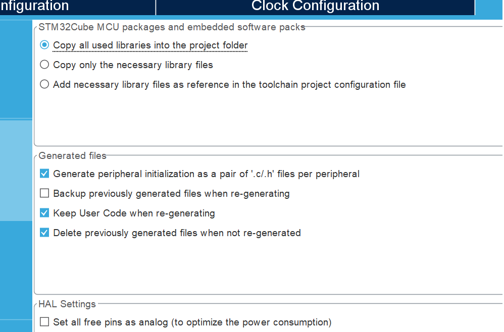
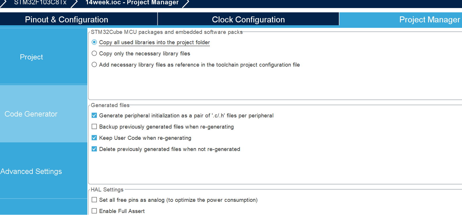
(9)项目配置
完成后生成文件
3、代码编写
1、打开生成的Keil文件
2、找到main.c文件,在文件中添加以下代码,该函数表示启动相应的定时器,“h”表示HAL库,“tim2”表示定时器2。所以这行代码的意思就是启动定时器2和定时器3。
HAL_TIM_Base_Start_IT(&htim2);
HAL_TIM_Base_Start_IT(&htim3);
3、在main.c文件中添加以下代码,定义STM32需要给上位机发送的消息。
uint8_t hello[20]="hello windows!\r\n";
4、在main.c文件中添加以下代码,表示定时器中断回调函数。
void HAL_TIM_PeriodElapsedCallback(TIM_HandleTypeDef *htim)
{
static uint32_t time_cnt =0;
static uint32_t time_cnt3 =0;
if(htim->Instance == TIM2)
{
if(++time_cnt >= 400)
{
time_cnt =0;
HAL_GPIO_TogglePin(GPIOA,GPIO_PIN_1);
}
}
if(htim->Instance == TIM3)
{
if(++time_cnt3 >= 1000)
{
time_cnt3 =0;
HAL_UART_Transmit(&huart1,hello,20,100000);
}
}
}
二、PWM实现呼吸灯
1、工程建立
(1)新建项目,选择本实验使用芯片stm32f103c8t6
(2)配置RCC
(3)配置SYS
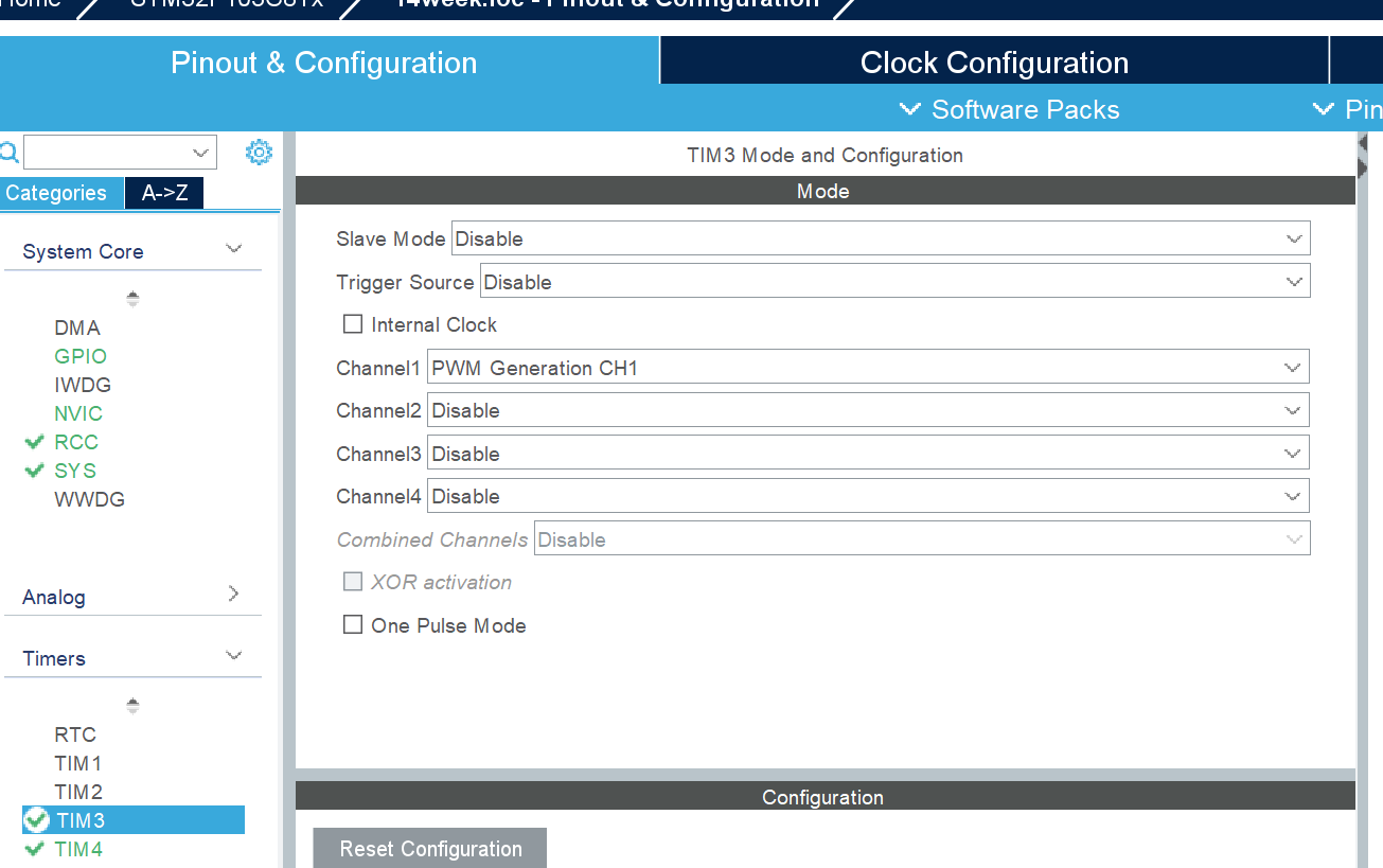
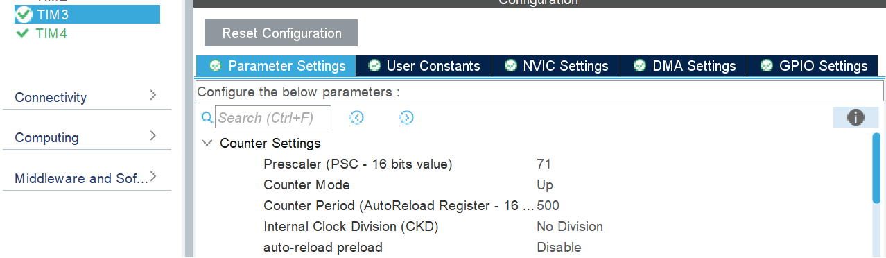
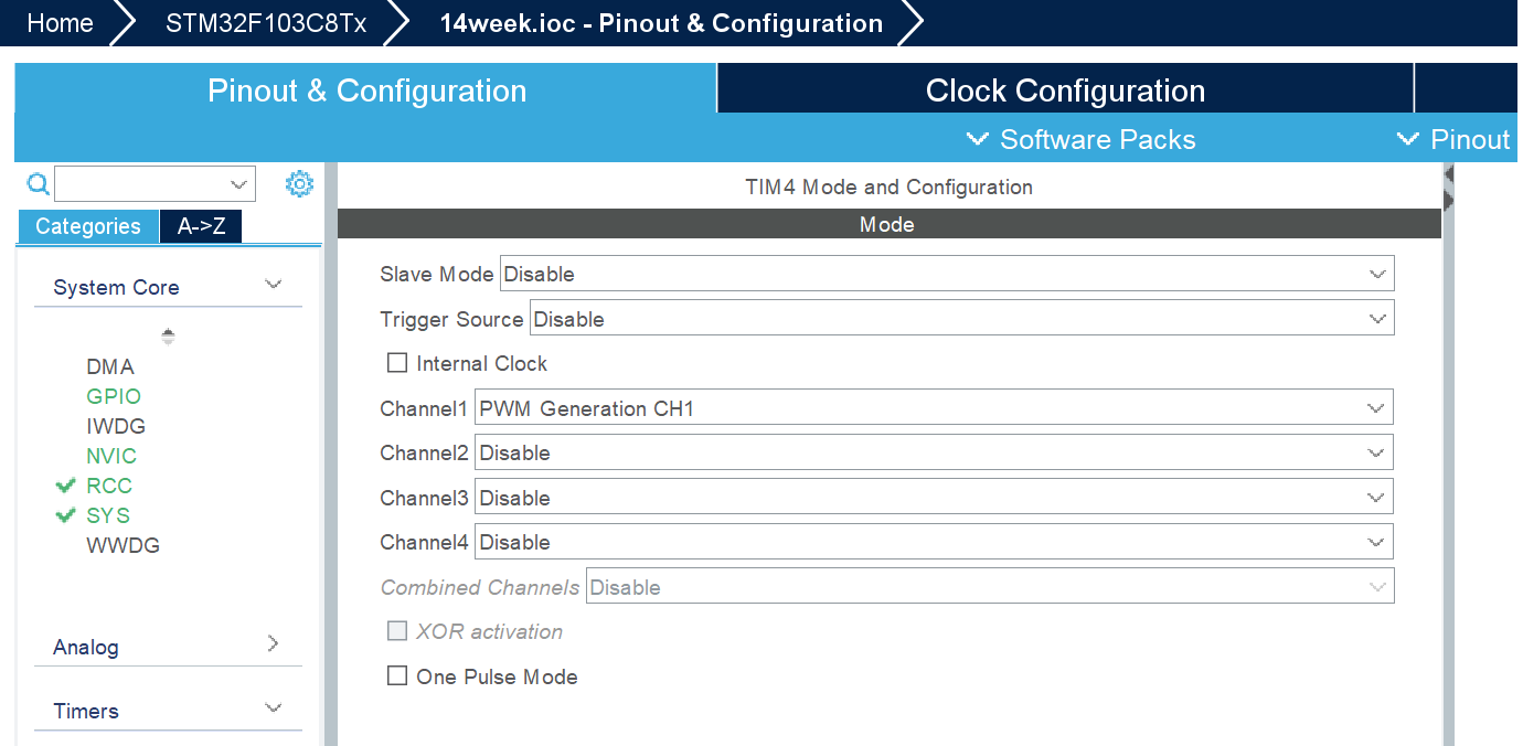
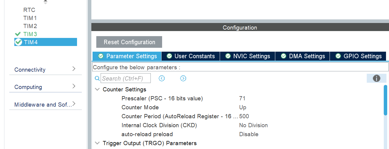
(4)配置TIM3和TIM4
(5)时钟配置
(6)项目设置
2、编写代码
(1)设置占空比,打开生成的Keil文件,找到main.c文件,在文件中添加以下代码:
uint16_t duty_num3 = 10;
uint16_t duty_num4 = 10;
(2)开始TIM3的通道3,输出PWM。
开始TIM4的通道4,输出PWM。
在main.c文件中添加以下代码:
HAL_TIM_PWM_Start(&htim3,TIM_CHANNEL_1);
HAL_TIM_PWM_Start(&htim4,TIM_CHANNEL_1);
(3)设置为每隔50毫秒,占空比加10,如果超过500(也就是PWM周期),自动变成0。(即灯会从亮倒暗,逐渐变化),在while(1)中添加以下代码:
/* USER CODE END WHILE */
HAL_Delay(50);
duty_num3 = duty_num3 + 10;
duty_num4 = duty_num4 + 10;
if(duty_num3 > 500)
{
duty_num3 = 0;
}
__HAL_TIM_SetCompare(&htim3,TIM_CHANNEL_1,duty_num3);
if(duty_num4 > 500)
{
duty_num4 = 0;
}
__HAL_TIM_SetCompare(&htim4,TIM_CHANNEL_1,duty_num4);
}
main.c文件完整代码:
/* USER CODE BEGIN Header */
/**
******************************************************************************
* @file : main.c
* @brief : Main program body
******************************************************************************
* @attention
*
* Copyright (c) 2024 STMicroelectronics.
* All rights reserved.
*
* This software is licensed under terms that can be found in the LICENSE file
* in the root directory of this software component.
* If no LICENSE file comes with this software, it is provided AS-IS.
*
******************************************************************************
*/
/* USER CODE END Header */
/* Includes ------------------------------------------------------------------*/
#include "main.h"
#include "tim.h"
#include "gpio.h"
uint16_t duty_num3 = 10;
uint16_t duty_num4 = 10;
/* Private includes ----------------------------------------------------------*/
/* USER CODE BEGIN Includes */
/* USER CODE END Includes */
/* Private typedef -----------------------------------------------------------*/
/* USER CODE BEGIN PTD */
/* USER CODE END PTD */
/* Private define ------------------------------------------------------------*/
/* USER CODE BEGIN PD */
/* USER CODE END PD */
/* Private macro -------------------------------------------------------------*/
/* USER CODE BEGIN PM */
/* USER CODE END PM */
/* Private variables ---------------------------------------------------------*/
/* USER CODE BEGIN PV */
/* USER CODE END PV */
/* Private function prototypes -----------------------------------------------*/
void SystemClock_Config(void);
/* USER CODE BEGIN PFP */
/* USER CODE END PFP */
/* Private user code ---------------------------------------------------------*/
/* USER CODE BEGIN 0 */
/* USER CODE END 0 */
/**
* @brief The application entry point.
* @retval int
*/
int main(void)
{
/* USER CODE BEGIN 1 */
/* USER CODE END 1 */
/* MCU Configuration--------------------------------------------------------*/
/* Reset of all peripherals, Initializes the Flash interface and the Systick. */
HAL_Init();
/* USER CODE BEGIN Init */
/* USER CODE END Init */
/* Configure the system clock */
SystemClock_Config();
/* USER CODE BEGIN SysInit */
/* USER CODE END SysInit */
/* Initialize all configured peripherals */
MX_GPIO_Init();
MX_TIM3_Init();
MX_TIM4_Init();
/* USER CODE BEGIN 2 */
HAL_TIM_PWM_Start(&htim3,TIM_CHANNEL_1);
HAL_TIM_PWM_Start(&htim4,TIM_CHANNEL_1);
/* USER CODE END 2 */
/* Infinite loop */
/* USER CODE BEGIN WHILE */
while (1)
{
/* USER CODE END WHILE */
HAL_Delay(50);
duty_num3 = duty_num3 + 10;
duty_num4 = duty_num4 + 10;
if(duty_num3 > 500)
{
duty_num3 = 0;
}
__HAL_TIM_SetCompare(&htim3,TIM_CHANNEL_1,duty_num3);
if(duty_num4 > 500)
{
duty_num4 = 0;
}
__HAL_TIM_SetCompare(&htim4,TIM_CHANNEL_1,duty_num4);
/* USER CODE BEGIN 3 */
}
/* USER CODE END 3 */
}
/**
* @brief System Clock Configuration
* @retval None
*/
void SystemClock_Config(void)
{
RCC_OscInitTypeDef RCC_OscInitStruct = {0};
RCC_ClkInitTypeDef RCC_ClkInitStruct = {0};
/** Initializes the RCC Oscillators according to the specified parameters
* in the RCC_OscInitTypeDef structure.
*/
RCC_OscInitStruct.OscillatorType = RCC_OSCILLATORTYPE_HSE;
RCC_OscInitStruct.HSEState = RCC_HSE_ON;
RCC_OscInitStruct.HSEPredivValue = RCC_HSE_PREDIV_DIV1;
RCC_OscInitStruct.HSIState = RCC_HSI_ON;
RCC_OscInitStruct.PLL.PLLState = RCC_PLL_ON;
RCC_OscInitStruct.PLL.PLLSource = RCC_PLLSOURCE_HSE;
RCC_OscInitStruct.PLL.PLLMUL = RCC_PLL_MUL2;
if (HAL_RCC_OscConfig(&RCC_OscInitStruct) != HAL_OK)
{
Error_Handler();
}
/** Initializes the CPU, AHB and APB buses clocks
*/
RCC_ClkInitStruct.ClockType = RCC_CLOCKTYPE_HCLK|RCC_CLOCKTYPE_SYSCLK
|RCC_CLOCKTYPE_PCLK1|RCC_CLOCKTYPE_PCLK2;
RCC_ClkInitStruct.SYSCLKSource = RCC_SYSCLKSOURCE_PLLCLK;
RCC_ClkInitStruct.AHBCLKDivider = RCC_SYSCLK_DIV1;
RCC_ClkInitStruct.APB1CLKDivider = RCC_HCLK_DIV1;
RCC_ClkInitStruct.APB2CLKDivider = RCC_HCLK_DIV1;
if (HAL_RCC_ClockConfig(&RCC_ClkInitStruct, FLASH_LATENCY_0) != HAL_OK)
{
Error_Handler();
}
}
/* USER CODE BEGIN 4 */
/* USER CODE END 4 */
/**
* @brief This function is executed in case of error occurrence.
* @retval None
*/
void Error_Handler(void)
{
/* USER CODE BEGIN Error_Handler_Debug */
/* User can add his own implementation to report the HAL error return state */
__disable_irq();
while (1)
{
}
/* USER CODE END Error_Handler_Debug */
}
#ifdef USE_FULL_ASSERT
/**
* @brief Reports the name of the source file and the source line number
* where the assert_param error has occurred.
* @param file: pointer to the source file name
* @param line: assert_param error line source number
* @retval None
*/
void assert_failed(uint8_t *file, uint32_t line)
{
/* USER CODE BEGIN 6 */
/* User can add his own implementation to report the file name and line number,
ex: printf("Wrong parameters value: file %s on line %d\r\n", file, line) */
/* USER CODE END 6 */
}
#endif /* USE_FULL_ASSERT */
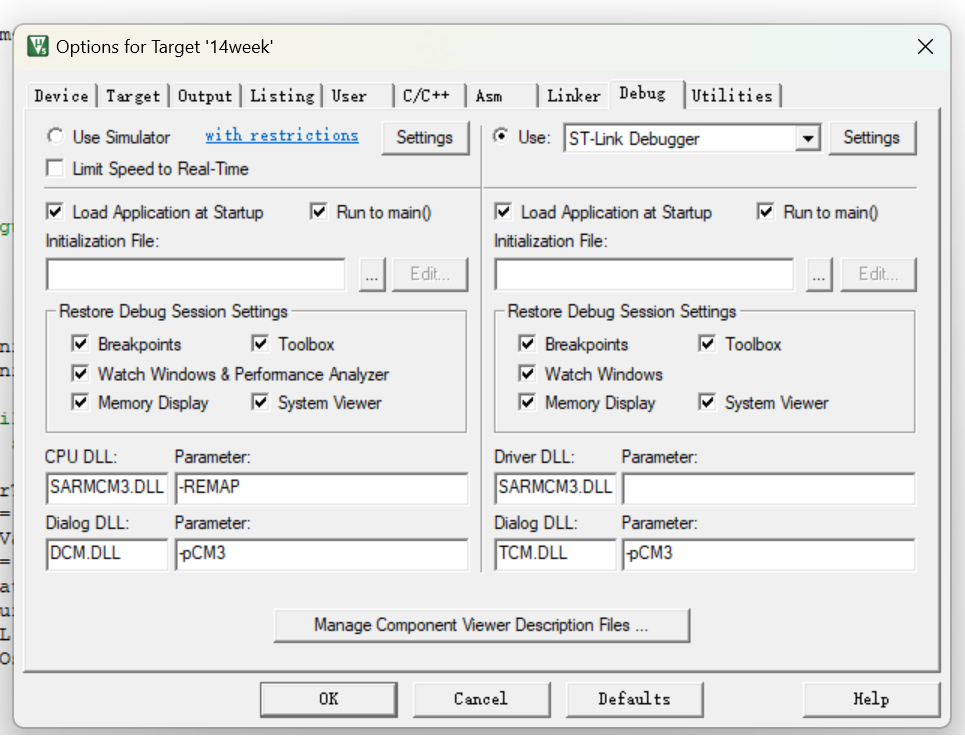
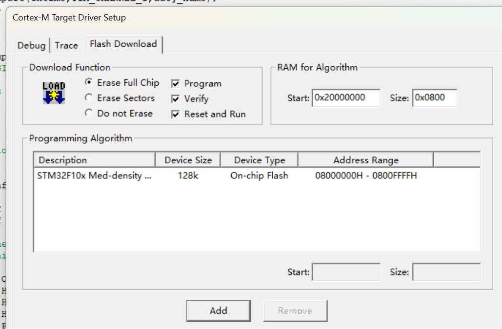
3、编译烧录
使用st-link进行烧录,注意先通过魔术棒改变设置
三、总结
通过这几个实验切实体会到了如何将 stm32 芯片的硬件功能通过软件代码配置来发挥作用。每一个功能模块都有对应的寄存器需要精确设置,而软件代码就是操作这些寄存器的 “钥匙”,只有正确配置才能让硬件按照预期工作,深刻认识到嵌入式开发中软硬件协同的重要性。
锻炼了调试能力
在实验过程中不可避免地会遇到各种问题,比如定时器中断不响应、串口接收的数据乱码、PWM 呼吸灯效果不符合预期等。这就需要借助调试工具,像使用示波器查看波形是否正确、通过串口调试助手检查发送和接收的数据情况等,逐步排查是硬件引脚连接问题、寄存器配置错误还是程序逻辑上的漏洞,这种调试经历极大地提升了自己解决问题的能力。
这些实验涉及到定时器、中断、串口通信以及 PWM 等多个知识点,它们之间相互关联又各有特点。通过实践,将原本书本上相对零散的知识整合起来,构建起一个较为完整的关于 stm32 应用开发的知识体系,明白了在不同应用场景下该如何选择和运用这些功能模块来实现具体的功能需求。

智能硬件社区聚焦AI智能硬件技术生态,汇聚嵌入式AI、物联网硬件开发者,打造交流分享平台,同步全国赛事资讯、开展 OPC 核心人才招募,助力技术落地与开发者成长。
更多推荐
 10
10 0
0- 0


 已为社区贡献2条内容

所有评论(0)